Voron 0.2 Kirigami Retrofit
Retrofitting a Voron 0.2 with the LDO Kirigami Bed Kit
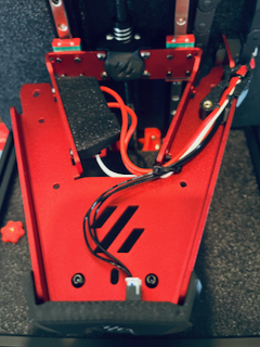
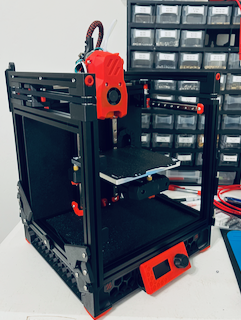
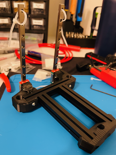
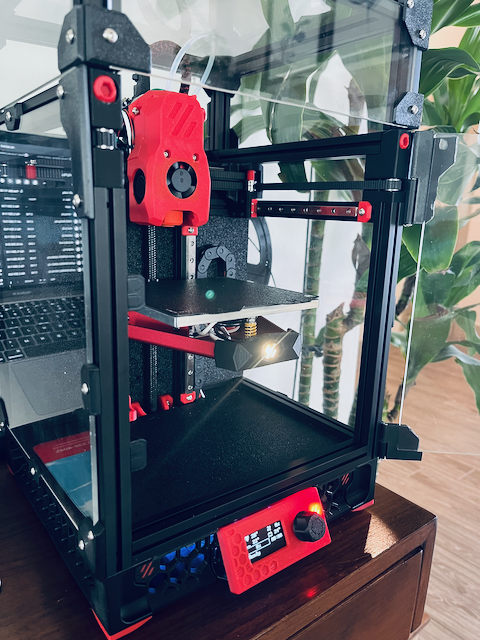
The original Kirigami bed can be found on GitHub. Per the creator, the idea was to implement a lightweight and stiff bed with full access to the mounting screws.” I started my Voron 0.2 build with the standard bed. After some issues requiring me to level the bed between each print, I upgraded to the Kirigami. I have outlined my process for retrofitting a Voron 0.2 with the stock bed to the LDO Kirigami kit.
Step 0: Install the Kirigami During the Initial Build
This would be the easiest option and clearly not what I did. However, if you’re looking at building a Voron 0 I strongly recommend going with the Kirigami off the bat.
Step 1: Print the Kirigami Parts
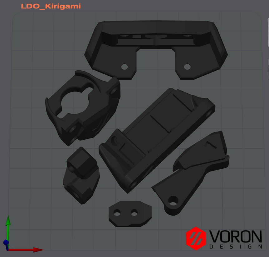
The original Kirigami printed parts can be found in the original project’s GitHub in the STLs folder. The LDO specific printed parts can be found in LDO Voron 0 Github under the STLs/Kirigami folder.
I printed the following parts for my retrofit:
| Kirigami Parts | LDO Parts |
|---|---|
| VORON_v0.2_stealth_nut_block.stl | Stealth_Bed_Main_Body.stl |
| VORON_v0.2_stealth_chain_mount.stl | Kirigami_LDO_Breakout_Mount.stl |
| VORON_v0.2_stealth_wire_guide.stl | [c]_Stealth_Bed_Diffuser.stl |
| VORON_v0.2_stealth_chain_mount_5mm_spacer.stl |
Although I didn’t end up using it, I still suggest printing VORON_v0.2_stealth_chain_mount_5mm_spacer.stl. It’s better to have it and not need it than need it and not have a working printer. Plus its less than a gram of filament. I didn’t end up printing [c]_Stealth_Bed_Diffuser.stl but that is only because I don’t have any clear filament at the moment.
Depending on your Voron 0, some of the other parts may be required but will not be covered here.
The LDO parts are designed to be used with the NeoPixel board, JST board, and WAGO terminals included in the LDO kit.
I printed all of the parts on my Voron 0.2 with Sunlu Black ABS using the Voron settings.
Step 2: Prep the Kirigami Parts
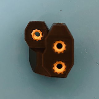
The LDO kit should include all of the hardware needed to install the bed. At this point, install the M3 heat set inserts into the printed parts.
- 4 inserts - Stealth Nut Block
- 3 inserts - Stealth Chain Mount
- 3 inserts - LDO Breakout Mount
- 2 inserts - LDO Stealth Bed Main Body
- 1 inserts - Stealth Wire Guide
After installing the inserts, snap the WAGO terminals into the LDO Breakout Mount and secure the JST breakout board with one of the included M3x6 screws. Pop the diffuser into the LDO Stealth Bed Main Body and secure the NeoPixel board with 2 M3x6 screws. Press fit 2 M3 nuts into the holes on the bottom of the LDO Stealth Bed Main Body.
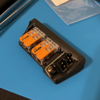
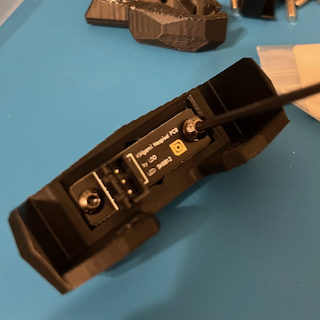
Once the printed parts are prepared, they can be mounted to the Kirigami bed with the included M3x6 screws. Mount the LDO Stealth Bed Main Body to the front of the bed. The Stealth Chain Mount and Stealth Wire Guide should mount to the right side of the bed, assuming that is where your cable chain is. The LDO Breakout Mount is mounted on the inside of the bed. I chose to mount it on the left inside with the terminals facing down.
Do not yet install the Stealth Nut Block.
Step 3: Removing the Stock Bed Assembly
Before proceeding, make sure the printer is turned off and has been unplugged from power for several minutes. The following steps involve disassembling parts of the printer and exposing the electronics.
To make these steps easier, I suggest starting by removing the tophat, side, rear, and bottom panels.
Remove the bed screws to free up the bed springs and heated bed. Remove the screws holding the cable chain to the bed assembly.
Hopefully, you have access holes in the mid panel the Voron. Assuming the holes exist, line the stock bed carriage up so the the M3 screws that secure the lead screw nut holder to the bed assembly can be accessed and removed.
If your mid panel does not have access holes, this step may require removal of the Z motor.
Next, remove the bolts holding the lead screw nut to the lead screw nut holder. If these steps were correctly completed, the bed assembly should now freely slide along the rails without the lead screw turning.
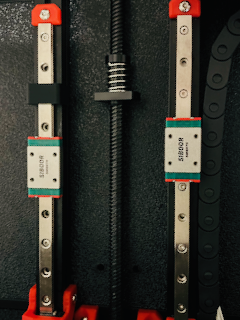
With the bed assembly freed up, remove the M2 bolts holding the Z rails to the frame.
Be careful when removing the rails to prevent the carriages from sliding off. I suggest using stoppers or zip ties to hold the carriages on the rails as they are removed.
Once the bed assembly and rails are removed, take all of the stock bed parts off so you are left with just the empty Z rails.
Take advantage of having the rails off and make sure they are cleaned and well lubricated.
Step 4: Prepare the Wiring
Now that the bed assembly is removed, it is much easier to access the cable chain.
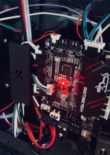
The LDO kit includes a precrimped wiring harness for the NeoPixel. One end should have a JST connector while the other should just be 3 free crimped ends. I applied a piece of heat shrink to the free ends to prevent them from snagging then pulled them through the cable chain to the mainboard.
With the NeoPixel wire at the mainboard, the included 3 pin JST connector housing can be applied to the free ends and plugged in. LDO was kind enough to color code the wires as follows.
| Red | 5VDC | |
| Black | GND | |
| White | DATA/IO |
Make sure the connectors are placed in the housing according to the pinout and interface on your board. I’m using the BTT SKR Pico and the pinout can be referenced here.
Since I’m already using the RGB connector, I elected to use the Servo connector. Note how the pinouts are different.
My stock bed was wired direct from the bed, through the cable chain, to the mainboard. The LDO kit includes WAGO terminals and a JST breakout to make the bed easily removable. I took this opportunity to run new thermistor and heated bed wires through the cable chain to take advantage of these connectors. Once I ran the new cables, the thermistor wire was terminated with a 2 pin JST connector on each end. I then crimped ferrules to each end of the heated bed wires.
Step 5: Install the Kirigami Bed
Loosely reinstall the bare Z rails to the printer. Once again, take care to make sure the carriages don’t slide off. If you still have the printed installation guides, these can be handy for lining up the rails properly.
With the liner rails installed, mount the Kirigami bed to the rail carriages. Use the included M2x4 screws. If you’re having issues, make sure the back bends of the Kirigami are 90 degrees and on the same plane. I don’t expect this to be much of an issue with a genuine LDO kit.
Once the bed is mounted to the Z rails, make sure it slides up an down the entirety of the rails without binding. Tighten the Z rails to the frame while moving the bed assembly up and down to make sure the rails are centered and no binding occurs.
Install the Stealth Nut Block by sliding it down the lead screw and securing it to the lead screw nut. Use the previously removed M3 screws and make sure the Voron logo is facing forward.
Slide the Kirigami bed into the Stealth Nut Block, line up the holes in the bed with the inserts in the Stealth Nut Block and secure it using the included M3x6 screws.
Step 6: Kirigami Cable Management
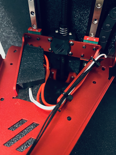
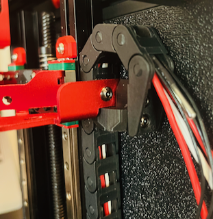
Reconnect the cable chain to the Stealth Chain Mount. Articulate the bed to check if a spacer is needed. In my case, I did not require the spacer but did have to an extra link to the cable chain. he included M3x6 screws are sufficient if no spacer is needed.
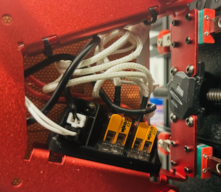
Route the heated bed, thermistor, and NeoPixel wires through the Stealth Wire Guide. Plug in the NeoPixel board. Plug the thermistor wire into the JST breakout and clip the head bed wires into the WAGO terminals. Make sure one wire goes into each terminal. There is a zip tie channel in the wire guide that can be used to secure the wiring. Use additional zip ties to manage the wiring in the Kirigami bed.
Step 7: Mount the Heated Bed
Verify the wiring on the heated bed. If using the JST breakout and WAGO terminals in the LDO kit, make sure the wires from the heated bed are an appropriate length. A thermal fuse should also be in place for added safety. Apply ferrules to the heater wires and a JST connector to the thermistor wire if needed.
Plug the thermistor into the JST breakout board and clip the heater wires into the WAGOs. Make sure to clip one heater wire into each WAGO. Route the wires as appropriate.
Install the heated bed to the Kirigami assembly using washers, bed springs, and the bed screws as per the standard Voron instructions. I needed to add an additional M3 nut to the bed screws to allow for enough spring compression. I also recommend starting with 1/2 to 2/3 compression in the springs.
Step 8: Verify Installation
Before replacing all the panels, I suggest running through a quick test process.
Powering up the printer with exposed electronics increase the risk of electric shock or damage to components.
Plug in and power on the printer. If Klipper and Mainsail/Fluidd start up with no errors, congratulations, you passed the first test.
Follow up by making sure the heated bed is reporting its temperature correctly. Next set the heated bed to 50°C and make sure the bed heats up as expected. Then turn off the heated bed and make sure it cools down.
If you encounter any errors, review the message and log file. Assuming everything worked prior to the install, the problem is likely related to the wiring. Double check the the runs and terminations to the heated bed and thermistor. Make sure each WAGO has the mainboard connected on one terminal and the heated bed connected to the other one. There is no polarity to worry about regarding these components.
Check the NeoPixel wiring by adding the following to printer.cfg.
1
2
3
4
5
6
7
8

[neopixel Stealth_Bed]
pin: gpio29 #Change this GPIO to the pin used on your board.
chain_count: 1
color_order: GRBW
initial_RED: 0.0
initial_GREEN: 0.0
initial_BLUE: 0.0
initial_WHITE: 1.0
Save & Restart the firmware. The NeoPixel on the bed should light up white. It should also be visible in the LED section of the frontend and controllable.
Once again, if it’s not working, verify the wiring and terminations. In this case, make sure the 5V, GND, and data pins are all connected to the proper pins. Double check the GPIO specified in printer.cfg is correct. I also discovered the endstop GPIO pins on the SKR Pico are unable to control NeoPixels.
Assuming everything is working, shut down the printer, unplug it, and put all the panels back on. The installation is officially complete.
Step 9: Calibration
The installation is complete but since we just made a major change to the printer, some recalibration is required. At minimum, make sure to set a new Z offset using the Z_ENDSTOP_CALIBRATE command and complete a rough bed level with the BED_SCREWS_ADJUST tool, then reconfirm the Z offset.
I elected to run a new PID tune on the heated bed for good measure.
It’s also a good idea to double check XYZ travel distances and the printable area. Especially since the Kirigami V3 has slots to allow for Y adjustment of the bed. Make sure to update Klipper and/or your slicer if needed.
We also changed a structural component of the printer. If input shaper is in use, it might also be a good idea to recalibrate that too.
I hope you enjoy the upgrade and happy printing!
References
In addition to the Voron and Klipper documentation, the following references were used during this installation and write up:
